VOYAGER
Voyager LECP Data Analysis Handbook
Instrument and Investigation Descriptions and Images
Engineering Design
- Detector Tests at Teledyne-Isotopes Using the
Pioneer F-08 RTG:
- Figure 1. Counting rate vs. distance, 100 micron detector
- Figure 2. Rough energy spectrum obtained at a distance of 26 cm
- Figure 3. Same as figure 1, for 200 micron detector
- Figure 4. Differential and integral energy spectrum for 200 micron detector
- Figure 5. Differential and integral energy spectrum for 100 micron detector
- Charged Particle Telescope diagram
- High Intensity Detector System for the Study of the Magnetospheres of Outer Planets:
Data File Descriptions
- EDR
- SEDR
- SEDR File (Tape) Layout
- Earth Mean Ecliptic and Equinox of 1950.0 (ECL50), Launch SEDR State Vectors
- Earth Mean Ecliptic and Equinox of 1950.0 (ECL50), Cruise SEDR State Vectors
- Earth Mean Ecliptic and Equinox of 1950.0 (ECL50), Jupiter Encounter State Vectors
- Earth Mean Ecliptic and Equinox of 1950.0 (ECL50), Saturn Encounter State Vectors
Calibrations and Channel Definitions
- Delta Detector Characteristics
- LEPT Logic and PHA Design
- Figure 1. Channels in the 5-150 micron combination for the coincidence condition (1 2 3).
- Figure 2. Channels in the 2-150 micron combination for the coincidence condition (0 2 3).
- Figure 3. Channels in the 150-2500 micron combination for the coincidence condition (2 3 4).
- Figure 4. Channels in the 100-2500 micron combination for the coincidence condition (5 4 3).
- Figure 5. Channels in the 100-2500 micron combination for the coincidence condition (5 4 3 2) and 5 4 3 2.
- Figure 6. Channels in the 2500-2500 micron combination for the coincidence condition (5 4 3 2) and 5 4 3 2.
- Time Constants for V1 LECP
- The Voyager LECP Pulse Height Analyzer (PHA)
- Block diagram of Pulse Height Analyzer for MJS-77 LECP Experiment
- LECP Pulse Height Analyzer data timing diagram
- Simplified peak detector block diagram; typical timing for peak pulse measurement
- Detailed circuit timing of LECP PHA A/D converter
- PHA basic error block diagram
- Schematic PHA 1520
- Schematic PHA 1530
- Schematic PHA 1540
- Schematic PHA 1550
- Schematic PHA 1560
- Schematic PHA 1570
- Internal Power Switches for LECP PHA system
- PHA test set - timing and control, data display
- PHA test set - digital servo control loop
- PHA test set timing diagram
- MJS-PHA test set data store, error sense and BCD conversion
- PHA test set display and control logic
- PHA test - miscellaneous schematics
- PHA test set - panel detail
- Specification - LECP Pulse Height Analyzer
- Rate Tests
- Random Pulser Test
- SN02
- Feb. 5, 1979, LECP SNO2, D1D2 Coincidence Strobe. Output Rate vs. Input Rate, Random Pulser Inputs ~1 MeV into Channels D1 and D2 (Rate Channel 3).
- α Channel
- β and β' Channels
- Channel A
Instrument Modeling Reports
- An Analysis of the Performance of the Magnetic
Deflection System in the Voyager Low Energy Charged
Particle Experiment (S. Shodhan master's thesis)
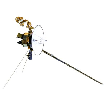
- Voyager spacecraft and scientific instruments
- A picture of the first flight unit of the LECP experiment
- Magnet configuration
- Projection of the magnets on the yz plane showing the rotated and the translated coordinate systems centered at each of the magnets
- Schematic drawing of the LEMPA and dome detector assembly
- Modeled sensor assembly for the LEMPA subsystem
- Projection of the modeled sensor assembly on the xy plane
- Projection of the modeled sensor assembly on the zy plane
- Projection of the beta housing on the yz plane
- Projection of the gamma housing on the yz plane
- The detector surface divided into several sampling areas
- Variation of the geometric factors with energy for the Gamma detector
- Variation of the geometric factors with energy for the Beta detector
- Points on the Gamma detector which are the initial points of the trajectories
- Points on the Beta detector which are the initial points of the trajectories
- Particle trajectories emanating from the point (-0.537177, -0.570312, 0.0) of the Gamma detector
- Particle trajectories emanating from the point (-0.718812, -0.09375, 0.0) of the Beta detector
- Angular distribution for energy E=720 keV
- Angular distribution for energy E=1440 keV
- Angular distribution for energy E=2880 keV
- Angular distribution for energy E=80 keV
- Angular distribution for energy E=320 keV
- Angular distribution for energy E=480 keV
- Angular distribution for energy E=320 keV
- Angular distribution for energy E=320 keV
- Points on the Beta detector which sample the area
- Projection of the field lines on the xz plane at y=04698 in.
- Projection of the field lines on the zy plane at x=0.0 in.
- Results of the observed and the calculated values of the magnetic field
- LEMPA Aperture Notes and Drawings
- LEMPA Telescope Assembly, detail from APL drawing 1D0600
- Configuration for Brazing, excerpt from APL drawing 1D0610
- β-γ Radiation Shields (excerpts from APL drawing 1D0612)
- LEMPA Field Control Cone (excerpt from APL drawing 1C0601)
- LEMPA Aperture Axial View (excerpt from APL drawing 1D0600)
- Sketch of the View Looking into the LEMPA Cone of the Backup Instrument
- LEMPA Magnetic Yoke, Sketch 1
- LEMPA Magnetic Yoke, Sketch 2
In-Flight Calibration Studies
- Study of Voyager 2 LECP Responses in Partial Exposure ("Chicken") Mode
Analyzed Observations
- Voyager Saturn Figures
- Voyager Saturn Studies (15 figures)
Saturn Operations
Return to Voyager
LECP Data Analysis Handbook Table of Contents.
Return to Fundamental
Technologies Home Page.
Updated 8/9/19, Cameron Crane
VOYAGER 1 ELAPSED TIME
--:--:--:--
Days: Hours:
Minutes: Seconds
*Since official launch
September 5, 1977, 12:56:00:00 UTC
*Since official launch
September 5, 1977, 12:56:00:00 UTC
VOYAGER 2 ELAPSED TIME
--:--:--:--
Days: Hours:
Minutes: Seconds
*Since official launch
August 20, 1977, 14:29:00:00 UTC
*Since official launch
August 20, 1977, 14:29:00:00 UTC
QUICK FACTS
Manufacturer:
Voyagers 1 and 2 were built in the Jet Propulsion
Laboratory in Southern California.
Mission Duration: 40+ years have elapsed for both Voyager 1 and Voyager 2 (both are ongoing).
Destination: Their original destinations were Saturn and Jupiter. Their current destination is interstellar space.
Mission Duration: 40+ years have elapsed for both Voyager 1 and Voyager 2 (both are ongoing).
Destination: Their original destinations were Saturn and Jupiter. Their current destination is interstellar space.


