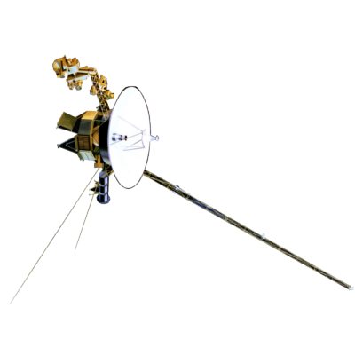
Voyager LECP Data Analysis Handbook
Calibrations and Channel Definitions
PHA Priority Scheme for the Voyager LECP Experiment
In discussion of the PHA priority scheme, the shorthand notation
L -> A-B-C
should be understood to mean that if the priority of the channel associated with the PHA data telemetered in the previous interval is L, then the "priority regime" is
A-B-C.
This A-B-C priority regime notation indicates that if the priority of the PHA data in the temporary buffer of the current interval is either B or C, then a newly incident, priority A ion will supersede these data and therefore the priority A data will be stored. If a subsequent priority A ion enters, the original priority A ion will remain. Additionally if the priority of the PHA data in the buffer is C and a priority B comes in, then the priority B will stored in lieu of the priority C data. As before, a subsequent priority B will not replace the existing priority B data. All of this is another way of saying that, in the current interval,
A-B-C
means that A has highest priority, B has intermediate priority and C has lowest priority. Note, in the following, that priority 1 channels consist of heavy ions, priority 2 channels are intermediate ions, and priority 3 channels consist of protons and alpha particles.
Three discussions of this priority scheme have been found:
Peletier: Peletier, D.P., et al., IEEE
Trans. Nucl. Sci., NS-24, No.1, 797, 1977
Krimigis: Krimigis, S.M., et al., Space Sci.
Rev., 21, 347, 1977
Table A7: PHA Enable Conditions from an APL document
Using the shorthand notation the priority schemes given in these three documents may be compared directly:
| Document | Priority Scheme | Comments |
| Peletier | 1 → 3-2-1 2 → 1-3-2 3 → 2-1-3 |
only even permutations assumed partially detailed in text explicitly detailed in the text |
| Krimigis | 1 → 2-3-1 2 → 3-1-2 3 → 1-2-3 |
explicitly detailed in the text explicitly detailed in the text explicitly detailed in the text |
| Table A7 | 1 → 2-3-1 2 → 3-1-2 (and 3-2-1*) 3 → 1-2-3 |
explicitly detailed in the table there may be a typo in the table explicitly detailed in the table |
*If the 2,1,1,YES row of the table is replaced with 2,1,1,NO, then Table A7 will agree with the Krimigis description in complete detail. As it stands the table implies that priority 3 data will replace buffered priority 1 or 2 data, but that priority 2 data will replace priority 1 and priority 1 will replace a priority 2.
Q: Is there a typo in table A7, and is Peletier's description wrong? If none are correct, what is the actual priority scheme?
Return to Calibrations main page.
Return to Voyager
LECP Data Analysis Handbook Table of Contents.
Return to Fundamental
Technologies Home Page.
Updated 8/9/19, Cameron Crane
VOYAGER 1 ELAPSED TIME
*Since official launch
September 5, 1977, 12:56:00:00 UTC
VOYAGER 2 ELAPSED TIME
*Since official launch
August 20, 1977, 14:29:00:00 UTC
QUICK FACTS
Mission Duration: 40+ years have elapsed for both Voyager 1 and Voyager 2 (both are ongoing).
Destination: Their original destinations were Saturn and Jupiter. Their current destination is interstellar space.


