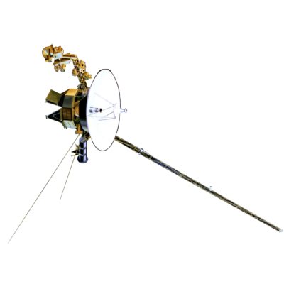
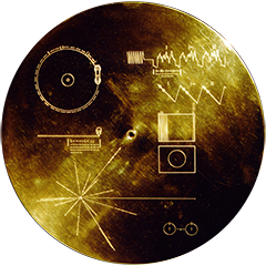
VOYAGER
Voyager LECP Data Analysis Handbook
Calibrations and Channel Definitions
The Voyager (MJS) LECP Pulse Height Analyzer (PHA)
References
- Proposal for Low Energy Charged Particle Measurements in the Jovian, Saturn, and Interplanetary Environments on the MJS 77 Spacecraft - August 1972; T. Krimigis (Principal Investigator)
- Technical Description of the Voyager Low Energy Charged Particle Instrument, D. Peletier (Project Engineer) et al.
- Paper: Mariner-Jupiter-Saturn Low Energy Charged Particle Experiment, Peletier, Gary and Hogrefe, 1976 Nuclear Science Symposium, New Orleans
Circuit Descriptions and Characteristics of EME Hybrids (all are Test Procedures):
| Hybrid No. | Type | Reference |
| EME-0274A | FET Switch - Type III | LECP-002-75A, 25 July, D. Fort |
| 0265A | FET Switch - Type II | as above |
| 0262A | Dual Discriminator | LECP-060-75A, 8 Jan. 76, S. A. Gary |
| 0266 | Precision Divider | EME-75-224, 8 Sept. 75, A. F. Hogrefe |
| 0267 | Peak Detector | EME-75-186, 5 Aug. 75, A. F. Hogrefe |
| 0268 | Unity Gain Buffer | EME-75-193, 12 Aug. 75, A. F. Hogrefe |
| 0269B | Negative Output Op Amp | EME-75-222, 8 Sept. 75, A. F. Hogrefe |
| 0270 | Positive Output Op Amp | EME-75-201, 19 Aug. 75, A. F. Hogrefe |
| 0263C | Dual One Shot | LECP-059-75A, 8 Jan. 76, S. A. Gary |
Return to Calibrations main page.
Return to Voyager
LECP Data Analysis Handbook Table of Contents.
Return to Fundamental
Technologies Home Page.
Updated 8/9/19, Cameron Crane
VOYAGER 1 ELAPSED TIME
--:--:--:--
Days: Hours:
Minutes: Seconds
*Since official launch
September 5, 1977, 12:56:00:00 UTC
*Since official launch
September 5, 1977, 12:56:00:00 UTC
VOYAGER 2 ELAPSED TIME
--:--:--:--
Days: Hours:
Minutes: Seconds
*Since official launch
August 20, 1977, 14:29:00:00 UTC
*Since official launch
August 20, 1977, 14:29:00:00 UTC
QUICK FACTS
Manufacturer:
Voyagers 1 and 2 were built in the Jet Propulsion
Laboratory in Southern California.
Mission Duration: 40+ years have elapsed for both Voyager 1 and Voyager 2 (both are ongoing).
Destination: Their original destinations were Saturn and Jupiter. Their current destination is interstellar space.
Mission Duration: 40+ years have elapsed for both Voyager 1 and Voyager 2 (both are ongoing).
Destination: Their original destinations were Saturn and Jupiter. Their current destination is interstellar space.


