


Voyager LECP Data Analysis Handbook
Engineering Design
S1P-857-72
January 7, 1972
TO: Team Members
FROM: S. M. Krimigis
SUBJECT: Summary of Detector Tests at Teledyne-Isotopes Using the Pioneer F-08 RTG
- Test set up
The PF-08 RTG unit was suspended from the ceiling and the detector was placed next to it on a wooden table. Measurements were performed in 4 differential and one integral channels, and a pulse height spectrum was obtained in most cases over the range 20 to 250 keV. The detectors were placed inside babbot (approximately 85 percent lead) holders and collimators with minimum shielding from any direction of approximately 0.25 inches (5.6 gm/cm2). The two detectors used were (a) 200 micron, 50 mm2 surface barrier with intrinsic noise of approximately 3.5 keV at room temperature and (b) 100 micron, 25 mm2 surface barrier with approximately 3 to 4 keV intrinsic noise at room temperature.
- Results
-
A. 100 micron detector
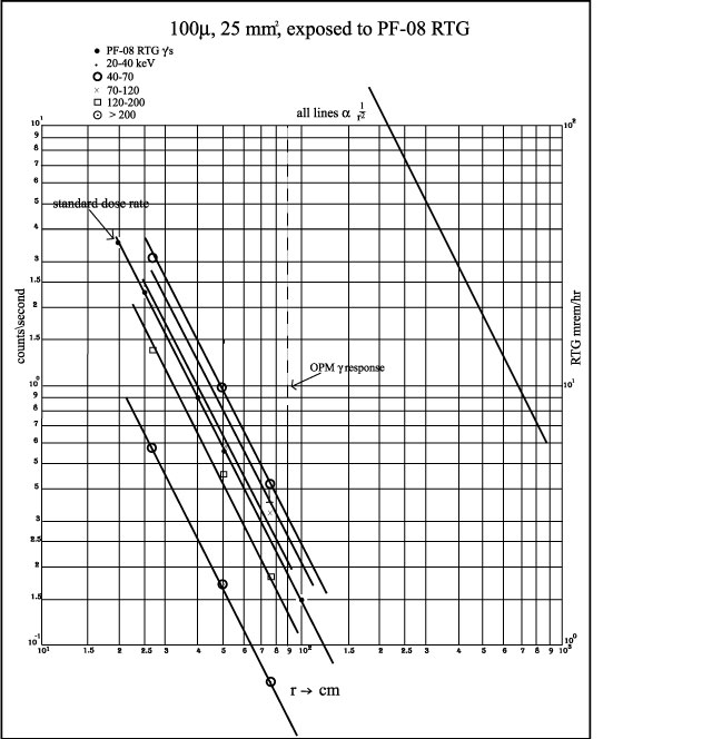
Figure 1 gives the counting rate vs. distance for the specified energy intervals for this detector. The dose rate due to γ's for the RTG is also shown. Using the JPL dose intensity contours it is apparent that the OPM rate is similar to that obtained from this RTG at a distance of approximately 85 cm. The counting rates for all detector channels is less than or equal to 0.3 c/sec with the highest channel less than or approximately equal to 0.06 c/sec. These rates are to be compared with approximately 0.5 c/sec due to omnidirectionally penetrating cosmic rays (although the effect of the differential channels may be to reduce the cosmic ray rate considerably, except for the last channel).
Conclusion - RTG interference for the 100 micron detector is not severe and is probably of the same level as the cosmic ray background.
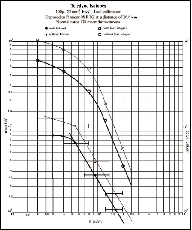
Figure 2 gives a rough energy spectrum obtained at a distance of 26 cm, with resolution similar to that expected from the flight data. The important facts are that (a) the differential spectrum flattens as one goes to lower energies and it may remain flat down to at least approximately 10 keV; (b) an additional shield of 0.25 inches of lead reduces the counting rate by approximately 40 percent at best; and (c) differential levels are preferable to integral ones from background considerations.
Conclusion - There should be no difficulty in setting levels down to approximately 10 to 12 keV from an interference standpoint. Also, it is probably not wise to invest any weight in shielding the detectors.
B. 200 micron detector
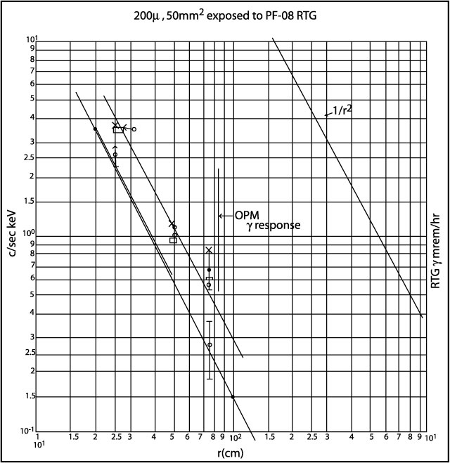
Because of noise problems, the data for this detector are not of good quality, but some conclusions which are consistent with the results using the 100 micron detector can be drawn. Figure 3 shows the same quantities as Figure 1, but for the 200 micron detector. The r-2 dependence is evident, although the scatter in the points is substantial, partly because of the poor statistics. Counting rates at OPM exposure levels are approximately 0.6 c/sec, i.e., a factor of 2 higher than for the 100 micron detector. These are again comparable with the expected cosmic ray background, but with the same qualifications expressed for the 100 micron detector.
Conclusion - The RTG interference for this detector is within acceptable limits.
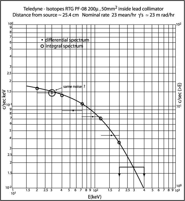
Figure 4 gives the differential and integral energy spectrum for this detector. It is noted that the drop-off at higher (greater than 50 keV) energies is not as fast as for the 100 micron detector, which is expected. Again, the advantage of differential over integral channels is quite obvious. Further, no turn-up in the spectrum is evident below 20 keV.
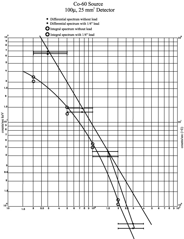
C. Comparison with Co-60 results
Figure 5 gives the differential and integral spectrum from the 100 micron detector using a nominal 1 mc Co-60 source at a distance of approximately 5 inches. It is seen that at higher energies (E greater than or approximately equal to 50 keV) the spectrum is not too different from the RTG one, but at low energies there is no plateau as is the case with the RTG. The detector was mounted in a thin aluminum can and it is seen that a shield 0.25 inches of lead decreased the counting rate by approximately 10 percent at best. Again, the same conclusion is reached, namely that investing weight in lead is probably unwise.
It is obvious that studies using a Co-60 source can be made which would yield upper limits to the level of interference expected from the OPM spacecraft RTG's.
- Additional Tests
Although the γ-ray dosage from the OPM RTG's is simulated at a distance of approximately 85 cm from PF-08, the expected neutron rate can only be achieved at a distance of approximately 25 cm from the same unit. All experimental evidence indicates that the detectors are affected by the γ-rays but not the neutrons. However, the total expected fluence of neutrons over 10 years is approximately 5 x 10¹⁰n cm-2, so that severe damage of the detectors could occur.
We must, therefore, irradiate the detectors at a sufficiently strong neutron source, so that the expected fluence can be simulated in a reasonable time period. Arrangements for this type of test are presently under way.
SMK:dl
Distribution:
Team members
JCrawford
JKohl
SAGary
RECashion
S1P Files
Archives/2
 |
|
 |
|
 |
|
 |
|
 |
Next: OPM Weight and Power Estimate
Return to Voyager
LECP Data Analysis Handbook Table of Contents.
Return to Fundamental
Technologies Home Page.
Updated 8/9/19, Cameron Crane
VOYAGER 1 ELAPSED TIME
*Since official launch
September 5, 1977, 12:56:00:00 UTC
VOYAGER 2 ELAPSED TIME
*Since official launch
August 20, 1977, 14:29:00:00 UTC
QUICK FACTS
Mission Duration: 40+ years have elapsed for both Voyager 1 and Voyager 2 (both are ongoing).
Destination: Their original destinations were Saturn and Jupiter. Their current destination is interstellar space.