


Voyager LECP Data Analysis Handbook
Engineering Design
High Intensity Detector System for the Study of the Magnetospheres of Outer Planets
C. Y. Fan
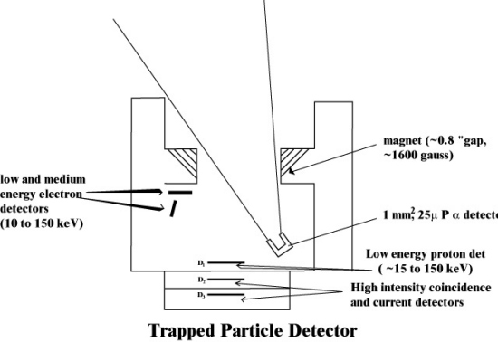
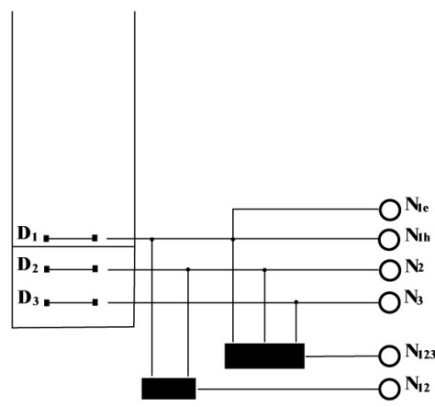
For the study of the shock transition regions and the radiation belts of outer planets, we propose to use a small 3 detector telescope. Using six rate outputs it should be possible to achieve (1) large dynamic range intensity measurements, (2) identification of high intensity protons and electrons, and (3) obtain limited spectral information. A stack of three AU-Si surface barrier detectors, designated as D1, D2, and D3, 25 mm2 in area and 200m in depletion depth, each is placed in a malloy-2000 (tungsten alloy) cylinder of 0.5 mm in wall thickness, to form a particle telescope of angle of acceptance 20 deg. (see Figure 1). A malloy-2000 absorber of 0.5 mm thick is sandwiched between D1 and D2 so that D2 and D3 are shielded against direct radiation. The outputs of the system will be (a) two counting rates from D1 at discrimination levels ~60 and 180 keV respectively (N1l and N1h), (b) one single rate each from D2 and from D3, both at discrimination levels of 60 keV (N2 and N3), (c) a D1D2 double coincidence rate (N12) and (d) a D1D2D3 triple coincidence rate (N123). To illustrate the characteristics of the system we consider the following five cases.
- Protons and electrons of energies less than 60 keV (i.e., likely populations in shock transition regions). In this case D1 will register the particles thru pile-up while D2 and D3 will not respond. Therefore, we would expect N1l to be greater than N1h while N2, N3, N12, and N123 have their values as in the interplanetary space.
- Electrons of energies between 0.06 and 1 MeV. In this case, D1 will be triggered by the electrons directly or by bremsstrahlung produced by these electrons in the spacecraft material. Since the range of 1 MeV electrons is ~0.8 g/cm2 in tungsten, D2 and D3 will be triggered only by the bremsstrahlung. Therefore, we would expect N1l to be greater than N1h, N2 ~ N3, N12approximately equal to or greater than 2t N1l N2, and N123 approximately equal to or greater than 3 t2 N1l N2 N3, where t is the resolving time. The last two equalities are due to the fact that N12 and N123 will be mostly accidental coincidences.
- Protons of energies between 0.06 and 17 MeV. In this case D1 will count the particles directly but D2 and D3 because of the shielding of the tungsten absorber will not respond. The expected rate pattern is then N1l ~ N1h while N2, N3, N12, and N123 still have their interplanetary or background values. This pattern distinguishes this case from case (1).
- Electrons of energies greater than 1 MeV. In this case, all three detectors will be triggered either by the particles directly or by the bremsstrahlung they produce. Consequently, the rate pattern will be N1l greater than N1h greater than N2 greater than N3; N12 greater than 2t N1 N2, and N123 greater than 3t2 N1 N2 N3.
- Protons of energies greater than 17 MeV. All the detectors will be triggered by the particles directly in this case. We would expect N1l to be greater than N1h greater than N2 greater than N3, N12 ~ F(AW)12 + 2t N1 N2, and N123 ~ F(AW)123 + 3t2 N1 N2 N3, where F is the flux and (AW)12 and (AW)123 are the geometrical factors for the double and triple coincidences respectively.
From the five sample cases, it is seen that this detector system is a compact but a versatile instrument for the study of the magnetospheres of outer planets. It provides for the detection of shock transition regions, makes a rough estimate of the populations of protons and electrons and their energies. The intensity range is covered through the use of double and triple coincidence counting techniques combined with a coincidence circuit having a resolving time 0.1 msec and a proper scaling factor, a dynamical range of ~106 can be achieved. Including current mode operation for some of these detectors a significant additional increase in intensity dynamical range would be achieved.
Next: MJS-77 Science Capability Review on July 29-30, 1975
Return to Voyager
LECP Data Analysis Handbook Table of Contents.
Return to Fundamental
Technologies Home Page.
Updated 8/9/19, Cameron Crane
VOYAGER 1 ELAPSED TIME
*Since official launch
September 5, 1977, 12:56:00:00 UTC
VOYAGER 2 ELAPSED TIME
*Since official launch
August 20, 1977, 14:29:00:00 UTC
QUICK FACTS
Mission Duration: 40+ years have elapsed for both Voyager 1 and Voyager 2 (both are ongoing).
Destination: Their original destinations were Saturn and Jupiter. Their current destination is interstellar space.